This is a presentation video for the freETarget build components. freETarget is an open-source project with the goal to allow anyone to build his or her own Electronic Scoring Target at a low cost. Approximate cost is ~300$. This includes buying the PCB board sets, but does not include the price of the tools necessary to craft the target.
Electronic Scoring Targets or ESTs are now the norm in sport shooting. Most competitions are shot on ESTs and they are actually mandated for some events, like air pistol and air rifle finals. A lot of local shooting clubs have now installed some sort of ESTs, especially in western europe.
There are a lot of manufacturers of ESTs. The biggest one, and the only one accredited by ISSF and so the only one usable in ISSF official competitions, is the swiss company SIUS. Other well known EST manufacturers are Meyton, Megalink, Intarso, SETA, Disag, Sport Quantum. Other less known manufacturers are Inband, Tachus, Noptel, Ariosoren, Kongsberg, Elite Scorer, Orion, Polytronic, Top Target System.


The median price for a single air pistol or rifle EST is around 2000 dollars. The cheapest EST that I could find is the Inband Air at 950 euros – but that is without the stand and the pellet trap.
There are 4 types of detection systems used by the ESTs:
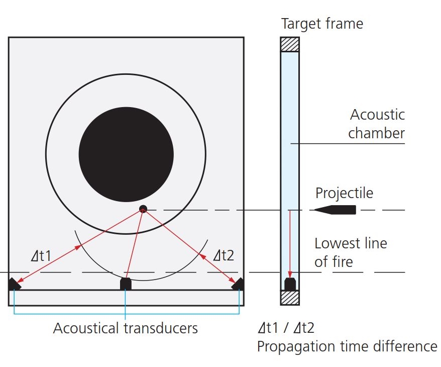


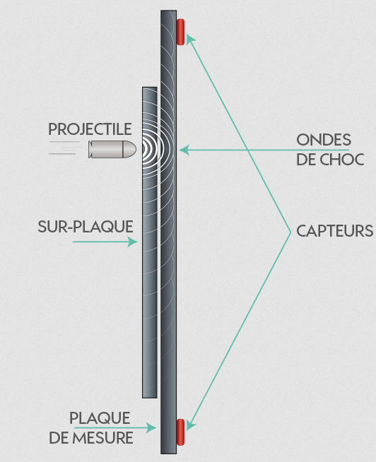
freETarget uses the sound based detection technology as it is the easiest to implement, requires fewer electronic components and has a good track record. The downside is that this technology requires a black paper roll to be scrolled after each shot. This makes it a consumable of the system, and so a constant cost in operating the EST.
The freETarget project is open source, meaning that all the development and the source code is public and free for anyone to view, modify and use. At the same time, a contributor to the project is not expected to provide support and is not obligated to help others with the use of the project.
This basically means that anyone looking to use the freETarget has to understand the technology being used and not to demand help or support from other contributors.
That being said, like in all open-source projects, there is a community built around the project with very helpful people that will provide answers and hints to those in need. There are 2 ways to get in touch with the community: via the github issue reporting tool: https://github.com/ten-point-nine/freETarget/issues and on the freETarget facebook group: https://www.facebook.com/groups/831490281129882
To build a freETarget EST, there are 4 main components: the electronics, the PC software, the Arduino firmware and the target itself.
The electronics consist of 5 small printed circuit boards with a microphone that act as detectors, and an Adruino shield board. The CAD files for these boards are published on the project github repository: https://github.com/ten-point-nine/freETarget . If anyone has the tools necessary to produce printed circuit boards from those files, is free to do so. If you are unable to, you can buy already made sets of boards by using the contact form on the project website: https://free-e-target.com/contact/
The PC software and the Arduino firmware are available for download on the project website: https://free-e-target.com/downloads/ or the source code can be viewed and downloaded from the github repository: https://github.com/ten-point-nine/freETarget
These components are the hardest to make and require expert knowledge. The main contributors of the project already took care of that.
The last component, also the bulkiest and that cannot be “transferred” via the internet, is the target itself. Every user of freETarget is required to build his or her own target housing and internal parts. It does not require electronics or software knowledge but it does require craftsmanship and some tools. Also, parts of the target components can be bought from normal stores like amazon.
The target can be split into different components:
- The stand: some sort of tripod where the target will be held up to the required 1.4 meters above the ground (for air pistol/rifle). This component is optional as the target can be mounted on a wall or other existing structure.
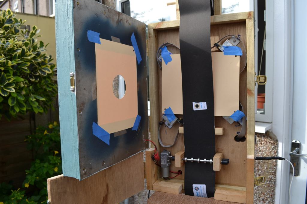
- The pellet catcher: this component is separate from the actual target but it has to be taken into consideration when building the target. The projectiles have to be stopped and/or deflected somewhere for safety reasons.
- The target box: the exterior shell of the target. This has to be built manually from OSB or plywood or metal. It usually has a back part and a door.
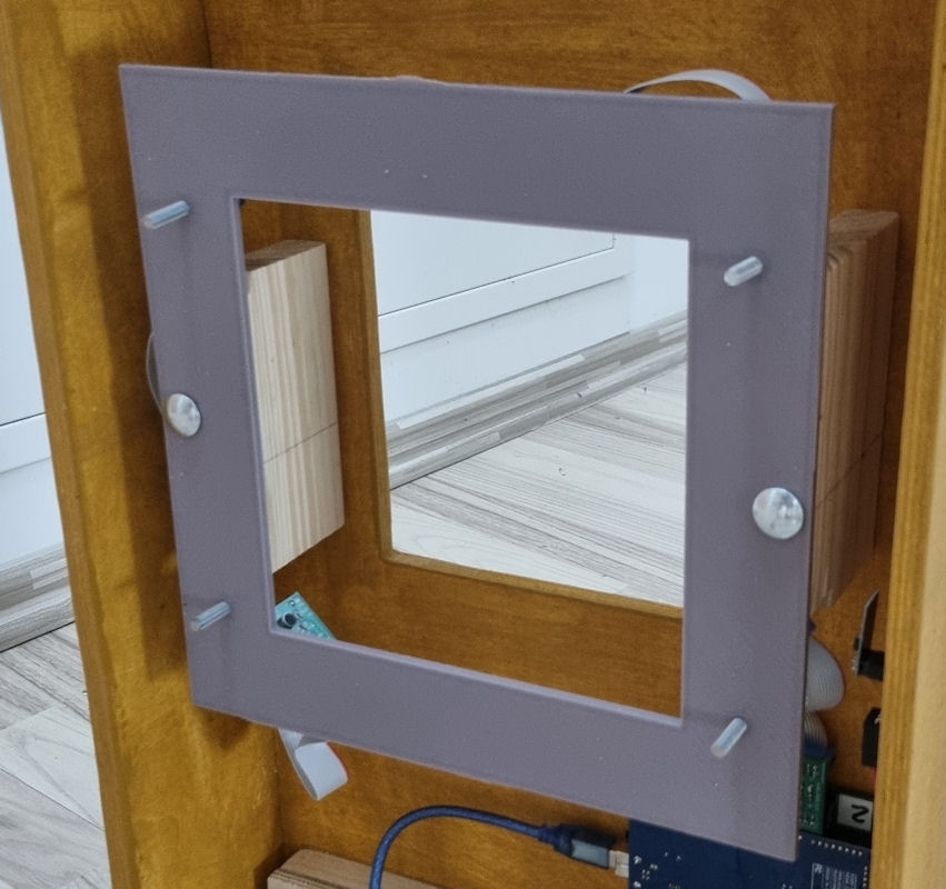
- The target frame: the frame where the sensors are mounted. This is a very critical part of the system, as the positioning of the sensors, relative to the other sensors and also to the paper mask is crucial for accuracy. The best, fastest and easiest method to make this component is to 3D print it. There are a few 3D models on the project website: https://free-e-target.com/community-made-piece-parts/ . The 3D printed frame still has to be mounted inside the box at the appropriate height on some manually built supports.
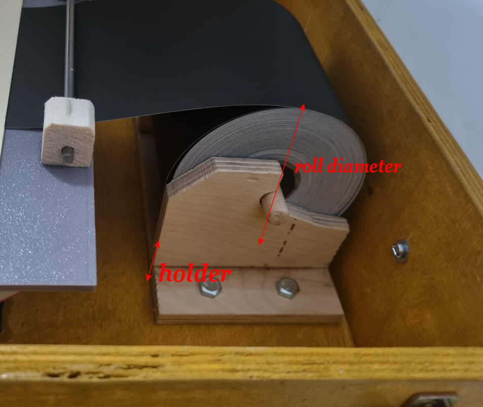
- The paper roll holder: the place where the black paper roll is held. It has to have a pin on which the paper roll is placed. The inner diameter of the paper roll hole is 12 millimeters, so the pin must be a bit smaller than that. Also, a full paper roll has a diameter of 90 millimeters – this makes the paper roll holder the thickest component and, if it is mounted inside the target box, it will determine the thickness of the target box. The pin and its holder can be built manually from wood or something similar.
- The paper motor plus rollers: a motor placed at the bottom of the target used to pull the black paper from the roll above through the paper mask in the middle. The motor can be either a simple DC motor or a stepper motor. The motor is linked with a coupling to a drive shaft with rollers. Another pinch shaft with rollers that is spring loaded will provide pressure on the paper so that the drive shaft can pull it. This is the hardest part to manufacture. More details on the application note pdf: https://allanbrownatl.files.wordpress.com/2021/08/using-witness-paper-3.pdf The motor and the roller can be bought online. There are some suggestions in the pdf. But the mounting supports for the motor and the shafts must be built manually from wood or something similar.
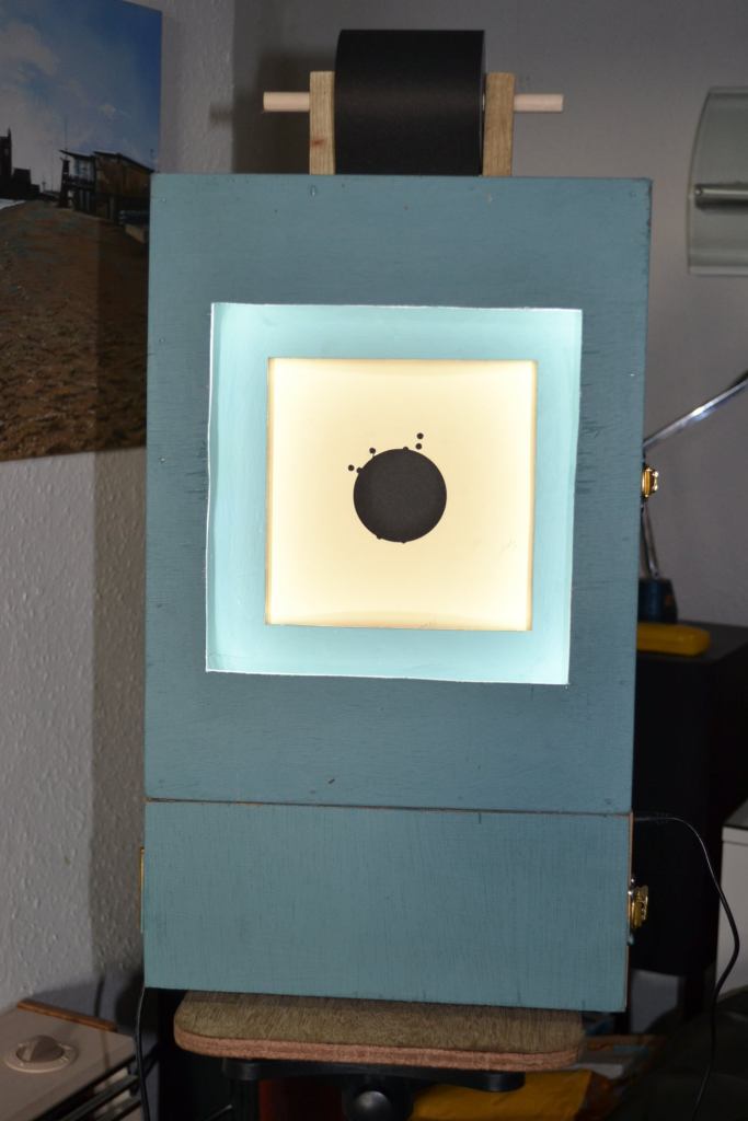
- The LED lighting: a LED strip that provides light on the paper mask. The ISSF regulation says that the light must be 1500 lux. The LED strip needs to be mounted in front of the paper mask, so it can be mounted on the target box door. But other placements are possible. More details on the LED operation can be found in the application note pdf: https://allanbrownatl.files.wordpress.com/2021/05/installing-the-target-light-1.pdf LED strips can be bought from amazon or other electronics shops.
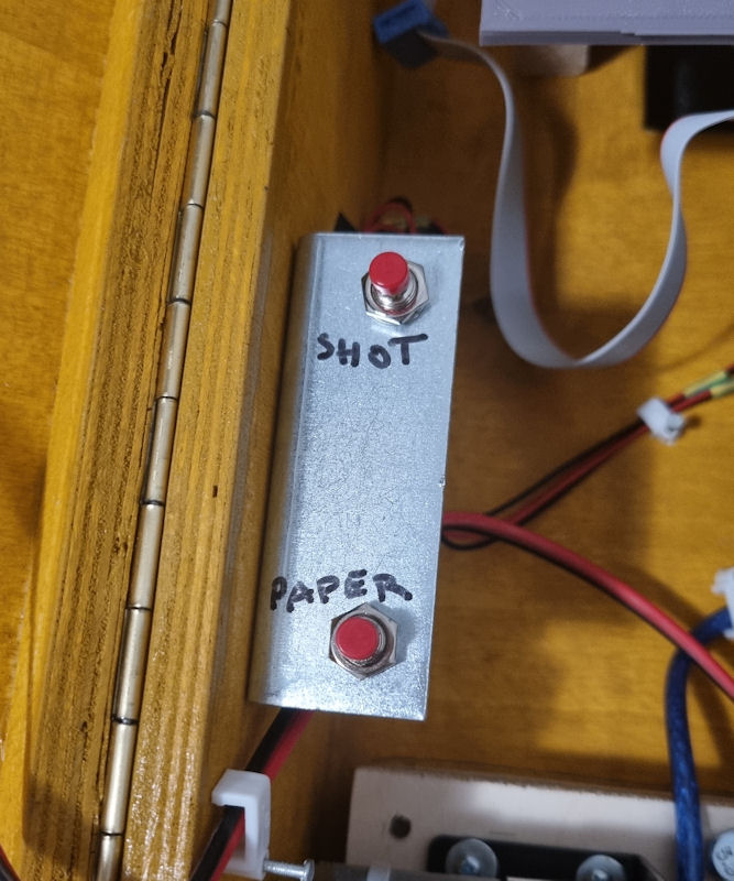
- The actions buttons: the system allows for 2 buttons to be present inside the box and their functionality is programmed in the arduino firmware. The most used functions are: one button to run the motor for a short period of time, in order to help load the paper, and one button to simulate a shot on the target, for testing purposes. Buttons can be acquired from normal electronic shops.
- The wifi module: a small ESP-01 circuit board that provides wireless connectivity for the target. More details and where to buy can be found in the application note pdf: https://allanbrownatl.files.wordpress.com/2021/07/going-wireless.pdf
More details on how to build and connect the different parts of the target can be found inside the technical documentation pdfs on the project website page: https://free-e-target.com/technical-documentation/


Here are sample steps on how to build and assemble the target (this is the way i did it. Other ways are possible):
- make the target frame. 3D printing is recommended. This holds the sensors and the paper mask and is the biggest component inside the target.
The dimension of the frame is dictated by the:
- Required diameter between sensors (230mm for air pistol)
- The paper mask – the white paper with a round hole in the middle where the black paper roll will scroll. There are multiple types of masks. I used the mask for SIUS. It’s dimensions are: 220 x 174 mm
- Determine the way the paper mask is attached to the target frame. It should be very close to the plane of the sensors, so there are no parallax errors. It is recommended 10 mm or less. With this frame, the sensors are one side of the frame and the mask on the other. The distance between them is circa 8 mm.
I chose to glue 1cm of threaded bar in the holes of the 3D print and use long nuts to secure the masks to the frame.
- Figure out how to mount the frame to the box. Here are the points to take into consideration:
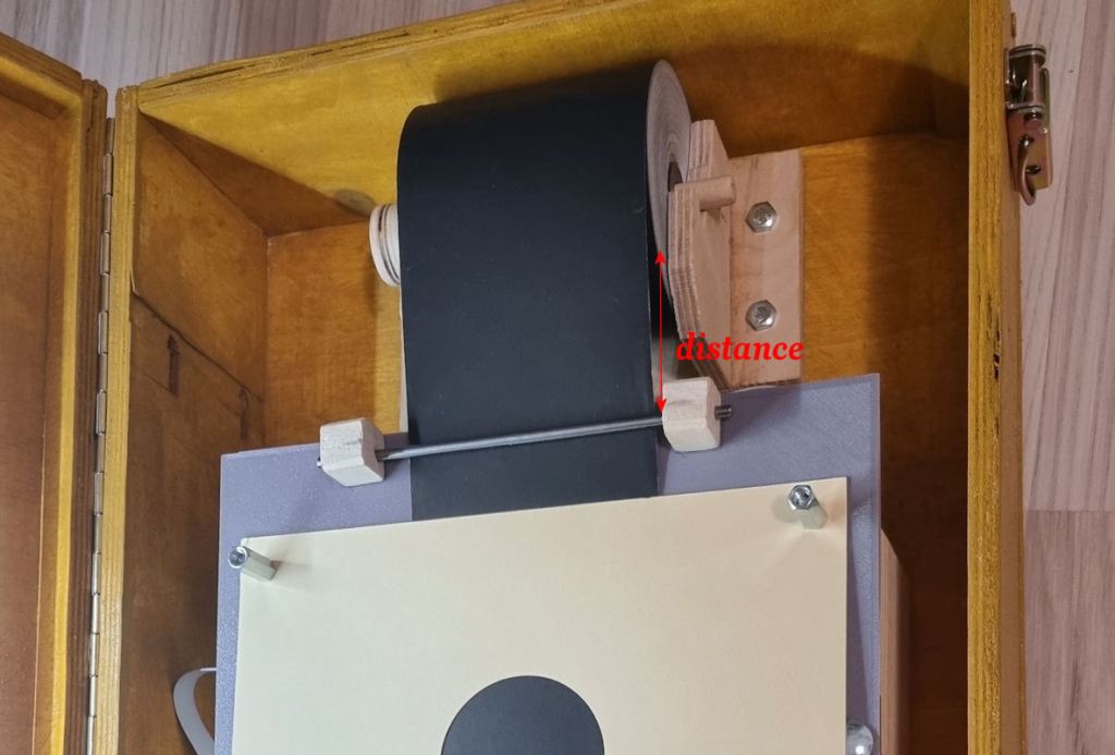
- the paper roll needs to flow on the paper mask. sharp angles will produce friction that will maybe jam the paper, so there has to be some distance between the roll and the frame
- The paper mask should be close to the box front
- The paper mask should be close to the LED strip
A guide rod for the paper can be installed on the top of the frame so that it will align the paper with the paper mask.
- Once the target frame has been built and it;s mounting figured out, it;s time to make the box. It’s dimensions are determined by:
- Height = the paper roll height + target frame height + arduino board height + motor height + some spare
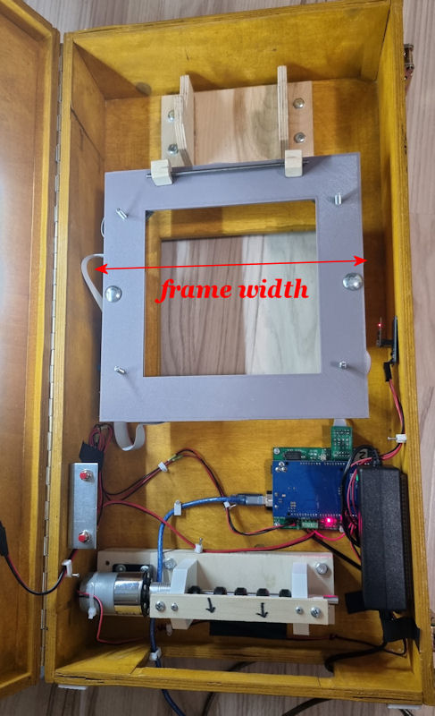
- Width = target frame width + some spare
- Depth = the paper roll + holder depth + some spare
The depth (thickness) can be separated in 2: the box and the door. The box has to have a big hole on the bottom, where the paper will roll out. Also it has to have a square hole 17x17cm in the front door and the back. This is where the projectiles will pass through.
- After the box is built, mount the paper roll holder
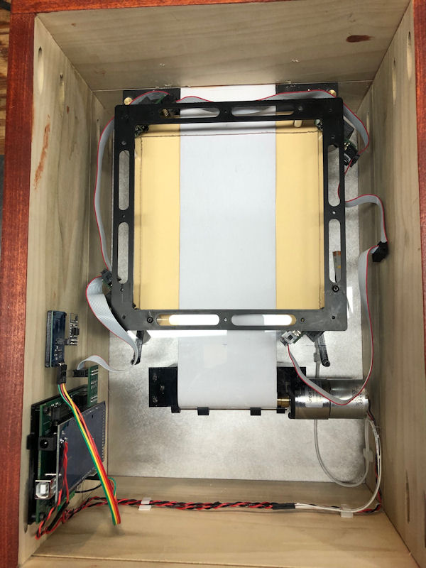
- Next is the mounting of the target frame.
- Next is fixing of the arduino + shield on the back of the box
- Next is the mounting of the motor assembly
- Next is the mounting of the buttons
- Next is the mounting of the LED strips to the door
- Last step is the connection of the wires from the sensors to the arduino, the wires from the motor, the buttons ,the LED and the power adapter to the arduino


After these steps, the target should be pretty much done. All that remains is to connect the USB to the arduino and plug in the power connector. For the operation of the PC software there will be another article.
Here are some pictures of other builds.
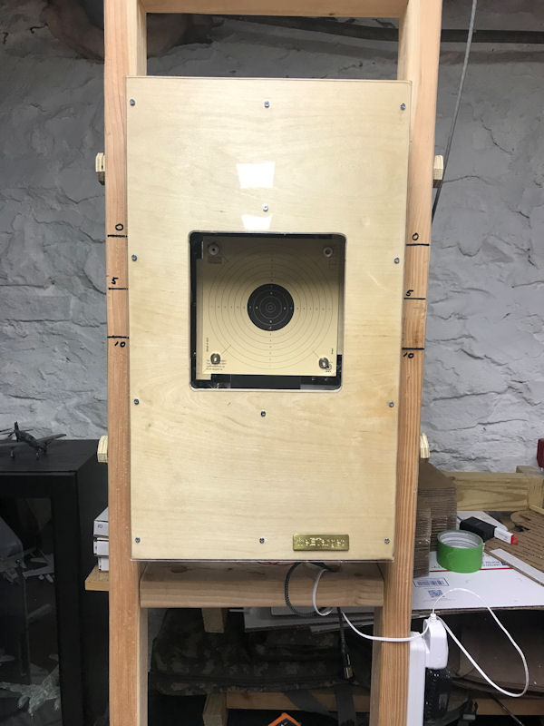


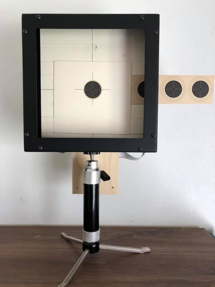


Have fun building your freETarget.
Similar articles:
– Electronic trainer: Trace
– Shooting glasses
– Romanian Gun Laws: who can own or conceal carry what types of guns [EN]
– Romanian gun laws [EN]
– PPC/WA1500: SR4″ match of 48 shots with a standard 4 inch revolver

Leave a comment